| Home | Software | Example Cases | Contact | Bio |
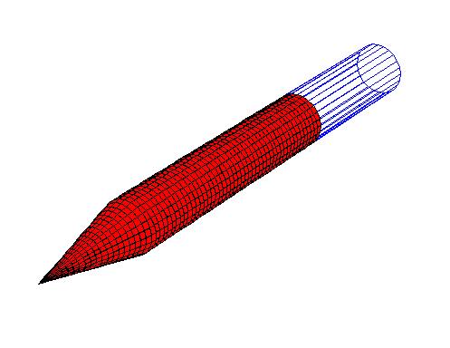
2 Caliber Cone with 4.6 Caliber Aftbody
The following results compare PANAIR and Euler results from AT CFD for a 2 Caliber Cone with an 4.6 Caliber aftbody. The PANAIR model includes panels on the base and a wake. The AT CFD model does not included a base. Instead, the body is extended a few body lengths aft of the base and the load is integrated only up to the axial location of the base.
The figure below shows the axial force coefficient (CX) vs. Mach number for an angle of attack of 5 degrees. The axial force coefficient is non-dimensionalized by the base area.
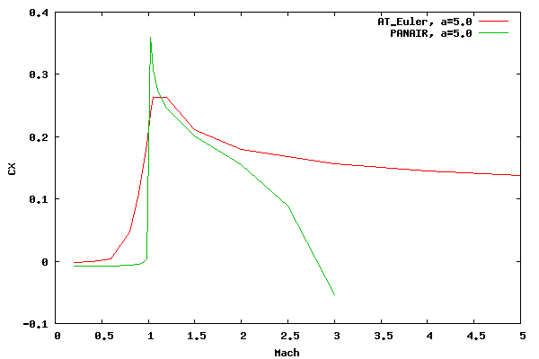
The CX values compare well at subsonic speeds below the critical Mach number and at low supersonic speeds. It must be noted that this comparison does not capture what is occurring on the aftbody since the axial force integration on the aftbody is zero.
The following graph presents the normal force coefficient (CZ) vs. Mach number for an angle of attack of 5 degrees. In addition, to get an idea of the nonlinearity of the Euler results, Euler results for 1 degree angle of attack are shown. To make the comparison, these results have been multiplied by 5. The PANAIR results are essentially linear so values at 1 degree angle of attack are not shown. It can be seen that the subsonic Euler results are linear, however the supersonic Euler results are not. This nonlinearity will become more pronounced as the angle of attack increases.
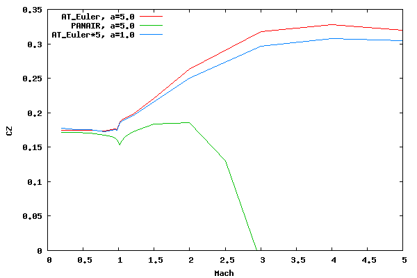
The subsonic results between PANAIR and AT CFD agree reasonably at subsonic speeds. However, for low supersonic speeds the comparison deteriorates. Reasons for the poor comparison are 1) the linearization of the potential equation causing poor load prediction on the aftbody, 2) the assumption of isentropic flow for the potential equation, 3) PANAIR's supersonic panel formulation causing slight forward influence, and 4) the slip boundary condition for AT CFD (as seen under the wedge comparison). However, I believe the first item above introduces the majority of the difference. Of course, as is expected, PANAIR (or any other "pure" panel method) does a very poor job at Mach numbers greater than 2.0. It should be noted that this statement applies to bodies rather than wings since, in general, bodies have more 3D (or volume) effects than wings. Wings are sometimes adequately modeled with expansion on the top and compression on the bottom.
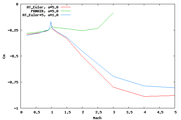
The following graph presents the pitching moment coefficient (Cm), which is non-deminsionalized by the base area and body diameter, for an angle of attack of 5 degrees. Once again, the Euler results for an angle of attack of 1 degree are shown, after having been multiplied by 5. The comparison observations are similar to that for CZ.
The following graph shows a comparison of the normal force distribution for PANAIR and AT CFD at an angle of attack of 1 degree and at Mach 1.5.
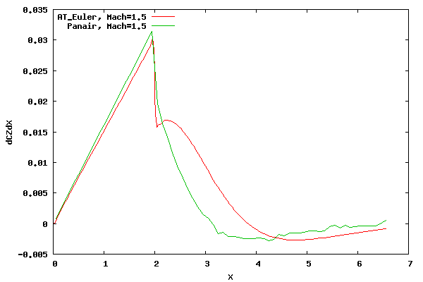
From the figure above it can be seen that the comparison is slightly different on the nose and even more so aft of the shoulder.
The PANAIR distribution on the nose differs from AT CFD since the Mach wave/cone (based on freestream Mach number) for PANAIR does not match with the shock wave/cone for AT CFD (the Mach wave lies closer to the surface than the shock wave) and the Mach cone does not pivot with the angle of attack as does the shock cone. Also, the assumption of isentropic flow for the potential equations introduces some error.
In regards to the aftbody, the issues with a linearized potential method are deeper. At the shoulder the PANAIR prediction expands through a Mach wave (which is based on the freestream Mach number and therefore parallel to the Mach wave from the cone apex), and the Euler prediction expands through a expansion fan. In addition, for PANAIR, the Mach wave from the cone apex is straight out to the farfield whereas the shock wave from the Euler model curves once the expansion fan intersects with the shock .
At some point in the future I hope to add results from a nonlinear velocity potential solver. It would be interesting to see how the assumption of irrotational and isentropic flow for the velocity potential equation effects the solution when compared to an Euler solution.